This example shows how to make a simple DC motor tester. We are using an analogue
input card with a linear potentiometer connected to its channel 4, a DC motor
controller card with a DC motor driver board connected to its channel 0. The address
of the Analogue input card is 6H, and a DC motor controller card is 3H.
If you turn the potentiometer from its middle position towards its end positions, the motor will turn CW and CCW. In fact, the motor speed and the turning direction will depend on the position of the potentiometer. When the potentiometer stays in the middle, then the motor doesn't turn.
In Visual Basic, just like in any other programming language, we need to be able to connect to ppds interfaces and communicate through them. The best way is to rewrite the PPDCommThread and PPDRIVER classes based on the cpphlib.py library. These two classes are enough for communication with the driver running on the virtual machine. The rewritten classes are located in cpphlib.vb file, which we have to add to our VB project.
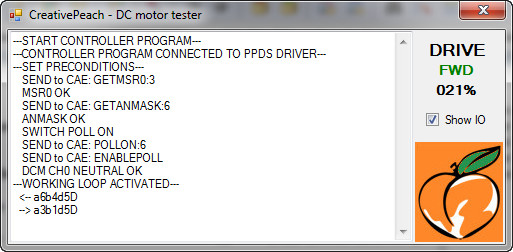
We create a simple windows Form application, create a textbox for display the debug log,
create a checkbox for show the IO data traffic and create
text displays to show the motor's driving parameters in that application.
The checkbox allows us to switch the IO debug on, when we want to see the data
traffic on the IO interface. When the controller program starts, it enables
the start timer in Form1_Load, so we can see in the textbox what happens at the
beginning. The timer tick event runs at once and it registers and connects to
the ppds interfaces. If connection is successful, it calls the Preconditions()
function. In this function the program checks the cards that
suit the control task in question (analogue mask must be 0X10 and MSR0 must
be set to 0X0A), and sets them up if it is necessary, and it finally switches
poll on. If preconditions are all OK, it activates the working loop. In the windows
applications which are event based, one of the easiest way of reading the input
changes is to use a timer event. The timer's event tmr_WorkingLoop_Tick() runs
every milliseconds and with the help of this function we can read the input queue
of the ppds IO interface. If queue has got data and the data comes from the analogue
input card's block 4, it means that we have turned the potentiometer. Then we must
calculate the display values from the incoming data and display them on user interface,
and create and send outgoing data to the drive the motor controller card. We must also
display the IO traffic when the checkbox is checked. When we click on Form, the window's
close button, the program runs the Postcondition() function, if the driver has been in
a connected state and if preconditions have run without errors. In Postcondition,
the program stops the DC motor independently from the position of the potentiometer.
After that the program switches poll to off and disconnects itself from the ppds
interfaces, writes messages in a textbox for that, and closes itself.
The function CAECommand can be used for sending commands to the CAE interface and
writing the passed command in the textbox. The function msg() is the logger, it
writes message in the textbox and also scrolls it automatically.
The example locates in dcmotor.zip in the dcmotor directory. Directory contains
a whole Visual Basic project with source codes, and compiled debug and release
exe files, etc. It can be downloaded from here.